Engine Cooler Assembly & Leak Test Automation
- Home
- Recent Projects
- Engine Cooler Assembly & Leak Test Automation
Project summary
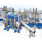
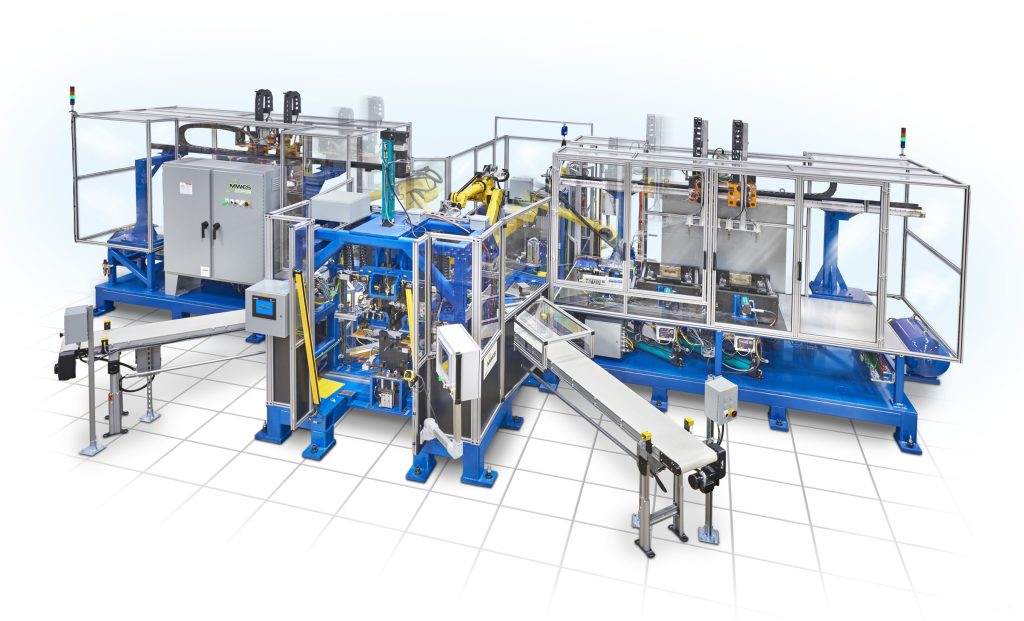
MWES provided this firm with a robotic automation system that assembles and tests diesel engine exhaust gas recirculation (EGR) coolers for a large automaker.
The Challenge
Recalling vehicles because of a defective part as the result of a faulty assembly process is the fear of all automakers and suppliers. That makes the tolerance of defective parts in the auto industry extremely low. To mitigate defects, engine component assembly systems require near-perfect consistency and extensive quality assurance testing. This firm contacted MWES to produce a semi-automated system to integrate into their engine component assembly line.
The Solution
MWES provided our customer with a semi-automated robotic assembly system. The system is built around a single robot that would transport in-process assemblies between three assembly stations. The first station is an offline semi-automatic dowl-to-shell press operation and manual O-ring assembly station followed by a core-to-shell marriage station. The assembly is then transported to a water-side leak test station. After leak testing, the robot transports the in-process assembly to the dial machine where the tank is assembled to the shell and the gas side is leak tested. If a reject occurs the robot moves the assembly to the reject conveyor and replaces it with a completed assembly from the buffer storage.
The assembly operation begins when the operator loads dowels into the press nest and sensors verify dowel presence. The operator then loads the shell to the press station and depresses two palm buttons—a pneumatic press ram advances to press both dowels into the shell. Travel switches will verify dowels are pressed to depth and the operator uses a load assist tool to install the two O-rings. Then the operator removes the assembled shell from the press and loads it to the core/shell marriage station.
The operator removes cores from dunnage storage and loads them to the press station. The operator then assembles the seal plate and clips it to the core. The operator then removes the shell from the station and loads it to an upper tooling nest. The operator depresses a palm button to initiate the inspection process. A series of sensors will determine the presence of O-rings, dowels on the shell, and seal plate and clips on the core. The 2D matrix barcode is applied to the shell and read. If all components are present, two independently actuated guides advance to assist in guiding the shell over the core clips. The press then advances to press the shell into the core. After the press operation, the press retracts and a part shuttle advances to present the assembly for robotic extraction. The robot removes the assembly from the shuttle and transfers it to the perch adjacent to the standalone leak test stations for leak testing.
At the leak test station, the 2D matrix barcode on the core is scanned and an overhead gantry captures the in-process assembly, changes hands and replaces it with a tested assembly. The gantry then transfers the untested in-process assembly to one of two leak test station shuttles. A servo-actuated floating C-Frame will advance an upper pad into contact with the top of the shell where the tank is attached and apply pressure. 20,000 lbs. of force is applied to the top of the shell to simulate bolt clamping. A horizontal slide will advance into contact with the water port. The pressure decay leak test unit will test the core for leaks. If the leak test is successful, a pneumatic impact stamp will stamp the shell with the letter “P”. If a reject condition exists, the assembly will be unloaded and placed onto the reject conveyor by the material handling robot.
The 4-stop indexing dial indexes a cooler assembly into position. The operator will load a gasket; tank and hand load six bolts to the cooler assembly and depress a palm button. A pneumatic torque spindle delivery slide advances a series of six torque spindles into engagement with the tank bolts. The tank bolts are run down, the slide retracts and the dial indexes the assembly to the nest. The dial indexes the fixture into position at the next stop and a robot tooled with a dual spindle torque gun arrangement torques the six bolts to 5nm. The dial indexes to the gas side leak test station with the final assembly complete. An overhead gantry advances to remove the in-process assembly from the dial nest. A tested assembly is placed on the dial nest while an untested assembly will be loaded to one of two leak test station shuttles. The shuttle retracts, and a vertical hold-down advances to stabilize the assembly and hold it against a seal pad. A pressure decay leak test operation is performed. If the leak test is successful, a pneumatic impact stamp will stamp the shell with the letter “G”. Reject assemblies are removed and placed in the reject shuttle and good assemblies are placed on the pack-out conveyor. The robot loads the completed and tested cooler assembly on a belt conveyor where the pack-out operator can retrieve it and perform a final inspection before finally packing it up.
Impact to the Customer
The semi-automated assembly and testing system MWES provided our customer gave them a highly accurate and safe manufacturing process. The system has an assembly cycle time of around 50 seconds from part to part.
Midwest Engineered Systems has a wide range of experience building automation systems for the automotive industry. If you’re looking to improve your assembly automation throughput, we have the knowledge and experience to make the project a success.
Contact us to learn how Midwest Engineered Systems can automate even your most complex and challenging operations today!
Innovation Through Automation
Client Details
A global parts manufacturer for automobiles and the EV industry.
