Hydraulic Motor Assembly Line
- Home
- Recent Projects
- Hydraulic Motor Assembly Line
Project summary
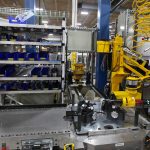
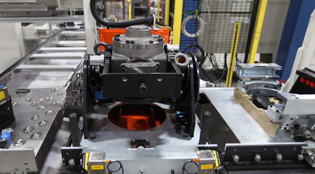
MWES provided a hydraulic motor manufacturer with an automated production line that handles the assembly of over a dozen different varieties of motors.
The Challenge
Building a single hydraulic motor production line that can handle the assembly of over a dozen different variations on a motor can be a logistical nightmare. On top of that, the progress of the total assembly from station to station needs to be tracked in real-time. This challenge can be met with a well-designed manual production line that can drive the assembly of complex motors efficiently.
The Solution
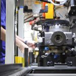
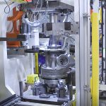
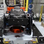
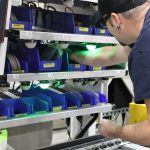
MWES built an assembly line for assembling several different varieties of hydraulic motors, all the while tracking the assembly progress at each station. The complete production line is broken up into a dozen sub-assembly stations where a different action is performed by an operator. The actions at each station can vary based on the specific variant of the motor that is currently being assembled. Once the motor is assembled, it goes to a finishing station where an operator installs and tests a potentiometer, and packages it as required.
The actions performed by the operators at each sub-assembly station:
- Cover Sub-Assembly Station
At this station, the operator assembles the distribution valve and covers and installs the bushings, thrust washers and seals to the housing. - Shaft and Bearing Support Sub-Assembly Station
At this station, the operator applies grease to the seals, then installs the seals and bearings to the shaft and the bearing support. This station will also be used to press the bearing race into the housings. - Block and Piston Sub-Assembly Station
At this station, the operator assembles the piston, roller and lunambules, then installs them into the block and installs the clips. A Keyence Vision system is used to verify the clip installation. - Assembly Line Station No. 1
At this station, the operator loads the shaft or bearing support into the pallet. For one of the variants, the operator manually loads and presses the block on the bearing support. - Assembly Line Station No. 2
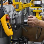
At this station, the Block sub-assembly mounting on the bearing support sub-assembly, along with the CAM mounting and bearing alignment tool mounting. The operator also installs the cover bolts and bearing support bolts, and rotates the positioning fixture as required for tightening the lower bolts. - Assembly Line Station No. 3
The operator installs the top bearing and rotates the motor while pressing the bearing until proper preload torque is achieved. The operator also measures the required split ring dimension through the servo press, installs the proper split ring, sets preload on tapper roller bearings, and verifies the final preload torque through the press. - Assembly Line Station No. 4
The operator mounts the expansion plug, shaft cover, and seals. For one variant, the operator installs the speed sensor with proper shimming before adding the brake housing and verifies of brake shaft. - Assembly Line Station No. 5
Installs required miscellaneous components. The brake’s final assembly and testing are based on the customers’ requirements. - Assembly Line Station No. 6
For two specific motor variants, the operator attaches the motor to an overhead carrier. The motor is then removed from the pallet and transferred manually to the next station. - Assembly Line Station No. 7
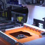
At this station, the motors are leak tested by submerging them in water, and then the operator looks for leaks evidenced by air bubbles in the water. - Assembly Line Station No. 8
All motors are tested here based on the customer’s provided testing standards. - Assembly Line Station No. 9
Oil is drained from the product and the operator unloads the assembly from the motor carriage. - Assembly Line Finishing Station
The installation and testing of the potentiometer sensor are one of the motors’ variants. The operator completes the assembly of the motor as required and packages it as required, including greasing the upper and lower pivots of the steerable motors.
Impact to the Customer
This production line greatly improved the customer’s efficiency in building hydraulic motors. With a part assembly cycle time averaging from 7 to 12 minutes, based in part on the operators’ abilities and the specific motor being assembled. Production throughput such as that is unmatched in the manual assembly of motors.
Midwest Engineered Systems has a wide range of experience in building hydraulic motor assembly lines. If you’re looking to improve your assembly line throughput, we have the knowledge and experience to make the project a success.
Contact us to learn how Midwest Engineered Systems can automate even your most complex and challenging operations today!
Innovation Through Automation
Client Details
A manufacturer of hydraulic motors.
